-
AuthorPosts
-
-
HID Fog Light Installation – GEN II (continued)

Wrap the split seam flex tubing around the wiring.

Install the HID fog lamps using the three 5/16” hex screws on each lamp base.

Both HID fog lamps installed in the fascia.

Clean the area inside the passenger side of the fascia. Remove the backing from the 3M dual lock on the HID ballast. Affix the HID ballast on the outside of the wheel well wall. Press firmly.

Connect the passenger side HID ballast power connector to the viper OE connector.

Repeat for the driver side.

Completed driver side.

Completed passenger side.

Position the fascia in front of the viper. Connect the driver side HID fog lamp wiring connectors to the connectors for the HID ballast. Connect the side marker lamp connections.

Repeat for the passenger side.
Turn the HID fog lights on to make sure that there are no issues with the new equipment (wiring, bulbs, ballast, etc). Contact the manufacturer/distributor if the new HID bulbs don’t illuminate.
Install the front fascia.
Done.
-
HID Fog Light Installation – GEN II
Parts:


- DDM Limited Edition Slim HID Xenon Conversion Kits, Wattage: 35, Bulb Type: H3, Bulb Color: 3000K (yellow)
- 1’ x 3M Dual Lock Reclosable Fastening System (super velcro)

- 2 x 2″ PVC DWV Flexible Cap – Model/Part# PQC-102 (Home Depot)
- 4 – 6 o-rings (OD 15/16”, ID 3/4”, 4 thickish – 1/8” or 6 regular – 1/10”) I suggest using high temperature o-rings, the responses that I received while inquiring about the expected HID fog light temperature were mixed
- 4 x 14-16 gauge Posi-locks (wire connectors)
- Electrical tape
- 3/8” x 4’ – Split seam flex tube
Tools:
- Protective pad/blanket
- Multi-purpose wiring tool
- Pliers (flat or needle nose)
- 5/16” socket or wrench

There are numerous color choices for High-Intensity Discharge (HID) lights. Here is the basic HID bulb color chart.I wanted to retain as many of the OE parts as possible in case there were issues with the HIDs. I wanted to keep the ability to return the fog lights to their original working condition. I also like a clean installation. The only OE part that needed to be used in a modified condition was the OE wiring harness on the bulb side of the connector. It needed to be cut so that it could be joined to the HID wiring harness.
Instructions:
Remove the front fascia. Place it on the protective pad/blanket.

Remove the OE fog lamps by removing the 3 5/16” hex screws on each lamp base.

Here is the fascia after the driver side fog lamp was removed and a few suicidal bugs were wiped off.

Pull the seal from the rear of the fog lamp. Squeeze and lift the bulb retainer wire away from the base of the bulb. Remove the seal, bulb and wiring. Disconnect both the brown (ground) and yellow (power) blade connectors.
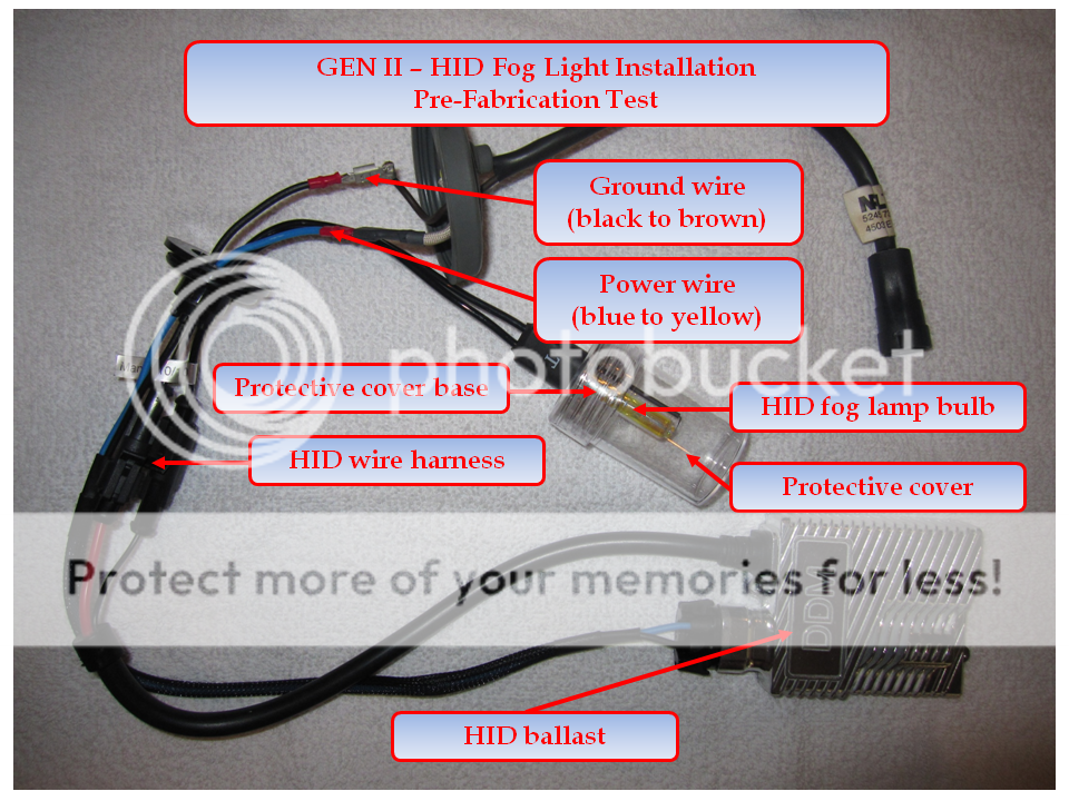
Connect the ballast to the HID wire harness. Connect the black (ground) and blue (power) blade feeds from the HID wire harness to the brown (ground) and yellow (power) connectors on the OE seal. Insert the OE wiring connector back into the feed on the viper. Turn the fog lights on to make sure that there are no issues with the new equipment (wiring, bulbs, ballast, etc). Contact the manufacturer/distributor if the new HID bulbs don’t illuminate.

This is the OE fog lamp with the seal, bulb and wiring removed.

There is a deflector located inside the fog lamp that keeps the light from being blinding. This view is down through the bulb base towards the outer fog lap cover.


The HID bulb is longer than the OE bulb and comes into contact with the deflector when it’s fully inserted into the bulb base. Place 2 or 3 o-rings into the bulb base to keep the HID bulb from coming into contact with the deflector. Compress the ends of the bulb retainer wire (use a pair of flat or needle nose pliers) to compensate for the HID bulb being partially backed-out of the bulb base.

Remove the HID bulb upper protective cover. Break and remove the protective cover base. Insert the HID bulb into the fog lamp base. Clamp it down with the bulb retainer wire. A little maneuvering of the bulb and wire may be necessary.

Use a sharp blade to cut a crosshair design in the new fog lamp base cover so that the HID bulb wiring can pass through the cover.

Cut the grommet off the HID bulb wiring harness. Pass the HID bulb connectors through the new fog lamp base cover so that the fog lamp is on the inside of the cover. Position the lamp cover over the lamp base.

The only part of the OE installation that needs to be modified is the power/ground wiring on the bulb side of the connector. One of mine was clearly cut and then butt connected together at the assembly plant. Snip these in the middle so that they can be joined to the new HID wiring harness and can also be returned to OE if needed.

This OE connector will be joined to the HID wiring harness. Snip the blade connectors off the HID wiring harness (blue and black wires). Cut the grommet off the HID wiring harness. This picture shows the HID bulb attached, but at this point it is already installed in the fog lamp.

Use the posi-lock connectors to join the wiring (power: blue to yellow, ground: black to brown). This picture shows the HID bulb attached, but at this point it is already installed in the fog lamp.

Use the electrical tape to tape the posi-lock connectors together.

Apply the 3M dual lock to the back of the ballast (two 3” strips).
-
-
AuthorPosts
- You must be logged in to reply to this topic.